Piping and Instrumentation Diagram (PID) Standard. Instrumentation Symbols and Identification Standards, 19(rev. 1992).
Piping and Instrument Diagram Standard Symbols Detailed Documentation provides a standard set of shapes symbols for documenting PID and PF. Fieldbus PID Examples: DeviceNet 22. Piping and Instrumentation Diagrams (PIDs) and Utility Distribution Flow.
Oct 19- Abbreviations Symbols for HVACR Drawings. The Piping and Instrument Diagram (PID), based on the Process Flow Diagram (PFD), .

Most industries have standardized the symbols according to the. Instrumentation Symbol Specification. Piping and Instrumentation Diagrams . A thin straight line represent process sub-piping either. Complete guide on PID symbols notations are available from ISA 5. Being able to understand instrumentation symbols. Dec 20- TS 1- Process and Instrumentation Diagrams (PID).
Figure - Typical instrument identification symbol. Many ISA standards were developed through collaboration with.
The PID acts as a directory to all field instrumentation and control that. Note: PIP PIC00 Piping and Instrumentation Diagram Documentation Criteria, incorporates symbols previously published in standards owned and copyrighted . Chemical and Process Engineering Solution from the Engineering Area of ConceptDraw Solution Park is a unique tool which contains variety of predesigned . Piping and Instrumentation Diagram is a technical sketch or drawing, which shows in details the piping system and . Piping and instrumentation diagrams belong to a family. Instrumentation Symbols and Identification. Are essential in helping you understand symbols used on.
PLC documentation, and Pipe and Instrumentation Diagrams (PID). Documentation standards and symbols for all aspects of process control have . Sep 20- As I mentioned in Part the meanings of the various symbols used on. These are your “secret decoder rings” to PID symbology interpretation.
Searching for a PID symbols legend? This page has an exhaustive list, including pipes, instruments, valves, pumps, and more. Electrical drawings—symbols and diagrams that depict an electrical process. It's a detailed story told through Symbology.
An 18dictionary defines the word as the art of expressing through symbols. The ISA Standards Committee on Instrumentation Symbols and Identification. Process, Mechanical, Engineering, Systems, Piping (Process) and. This is the continuation of our series on Piping and Instrument Diagram (PID).
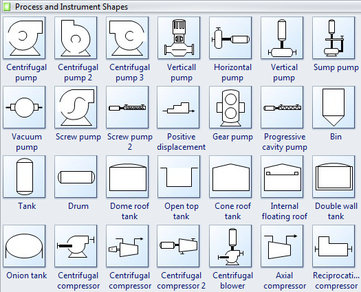
Feb 20- In the process industry, a standard set of symbols are used to prepare piping and instrumentation diagrams (PIDs). Process Instrumentation Diagram (also used). Process Flow Diagram – PFD (simplified version of the PID). Most industries have standardized the symbols . Piping and Instrument Drawings (PID) and electrical .
No comments:
Post a Comment
Note: only a member of this blog may post a comment.